IBGP Load Balancing with BGP Additional Paths
In the previous lab exercise, you implemented IBGP load balancing across prefixes received by two WAN edge routers. The load balancing worked because you did not use BGP route reflectors in your autonomous system. Like any other BGP router, BGP route reflectors send their best routes to their clients; in your network, the IBGP clients of the BGP route reflector receive a single path to the external prefix.
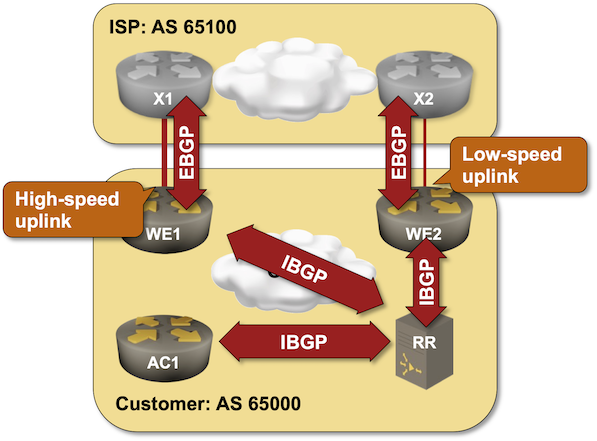
You can use the BGP Additional Paths functionality to make the BGP route reflector send more than one BGP path for the same IP prefix to its clients, resulting in IBGP load balancing on BGP route reflector clients. You’ll practice that in this lab exercise.
Existing Device Configuration
The routers in your lab use the following BGP AS numbers. Each router router advertises an IPv4 prefix.
| Node/ASN | Router ID | BGP RR | Advertised prefixes |
|---|---|---|---|
| AS65000 | |||
| ac1 | 10.0.0.4 | ||
| rr | 10.0.0.3 | ✅ | |
| we1 | 10.0.0.1 | ||
| we2 | 10.0.0.2 | ||
| AS65100 | |||
| x1 | 10.0.0.10 | 192.168.42.0/24 | |
| x2 | 10.0.0.11 | 192.168.42.0/24 |
Your routers (RR and AC1) have these EBGP neighbors.
| Node | Router ID / Neighbor |
Router AS/ Neighbor AS |
Neighbor IPv4 |
|---|---|---|---|
| ac1 | 10.0.0.4 | 65000 | |
| rr | 65000 | 10.0.0.3 | |
| rr | 10.0.0.3 | 65000 | |
| we1 | 65000 | 10.0.0.1 | |
| we2 | 65000 | 10.0.0.2 | |
| ac1 | 65000 | 10.0.0.4 |
All routers run OSPF in the backbone area on intra-AS interfaces.
netlab automatically configures device interfaces, OSPF, and BGP; if you’re using another lab infrastructure, you’ll have to configure lab devices manually.
Device Requirements
- Use any device supported by the netlab BGP configuration module for AC1 and RR.
- Use a device on which netlab supports BGP link bandwidth attribute (for example, FRRouting, or Arista EOS) for external devices (X1, X2, WE1, WE2)
Start the Lab
You can start the lab on your own lab infrastructure or in GitHub Codespaces (more details):
- Change directory to
lb/4-ibgp-add-path - Execute netlab up
- Log into your devices with netlab connect and verify that the IP addresses, OSPF, and EBGP sessions are properly configured.
Warning
This lab exercise requires netlab release 1.8.3 or later.
The Problem
The BGP route reflector (RR) receives a path toward 192.168.42.0/24 (with BGP link bandwidth) from WE1 and WE2 and could do weighted load balancing across the two paths if configured to do so (see IBGP Load Balancing with BGP Link Bandwidth for more details):
rr>show ip bgp 192.168.42.0
BGP routing table information for VRF default
Router identifier 10.0.0.3, local AS number 65000
BGP routing table entry for 192.168.42.0/24
 Paths: 2 available
  65100 (Received from a RR-client)
    10.0.0.1 from 10.0.0.1 (10.0.0.1)
      Origin IGP, metric 0, localpref 100, IGP metric 10, weight 0, tag 0
      Received 00:48:45 ago, valid, internal, best
      Extended Community: 0004-AS:65000:125000000
      Rx SAFI: Unicast
  65100 (Received from a RR-client)
    10.0.0.2 from 10.0.0.2 (10.0.0.2)
      Origin IGP, metric 0, localpref 100, IGP metric 10, weight 0, tag 0
      Received 00:48:40 ago, valid, internal
      Extended Community: 0004-AS:65000:250000000
      Rx SAFI: Unicast
The BGP routing process in the BGP route reflector selects a single best path and advertises it to its clients. AC1, therefore, receives one of the paths advertised by WE1 and WE2 and never uses more than one exit point from AS 65000. Even worse, all route reflector clients use the same exit point.
ac1>show ip bgp 192.168.42.0
BGP routing table information for VRF default
Router identifier 10.0.0.4, local AS number 65000
BGP routing table entry for 192.168.42.0/24
 Paths: 1 available
  65100
    10.0.0.1 from 10.0.0.3 (10.0.0.3)
      Origin IGP, metric 0, localpref 100, IGP metric 10, weight 0, tag 0
      Received 00:50:18 ago, valid, internal, best
      Originator: 10.0.0.1, Cluster list: 10.0.0.3
      Extended Community: 0004-AS:65000:125000000
      Rx SAFI: Unicast
Note
Most BGP implementations do not consider the BGP link bandwidth attribute when selecting the best path. The path advertised to the route reflector clients could be the worst path toward an external destination.
To enable load balancing in our network, we need the capability to advertise more than just the best BGP path to route reflector clients – the BGP Additional Paths functionality.
Configuration Tasks
BGP Additional Paths is an optional functionality that must turned on with a configuration command and negotiated between BGP neighbors. Some BGP implementations have granular control over the sending and receiving of additional paths and the ability to select which paths to send. We’ll use the most straightforward approach:
- Configure RR to send additional paths to all route reflector clients using a configuration command similar to neighbor additional-paths. RR does not have to receive additional paths; we expect all edge routers to send a single best path.
- If needed, configure AC1 to accept additional paths.
- (Optional) Configure IBGP load balancing on RR and AC1 using commands you mastered in the IBGP Load Balancing with BGP Link Bandwidth exercise.
Warning
Configuring BGP Additional Paths on a BGP neighbor tears down the BGP session as the additional capability has to be negotiated. Schedule a maintenance window before introducing BGP Additional Paths into a production network.
Verification
After configuring BGP Additional Paths on AC1 and RR, you should see two paths for the prefix 192.168.42.0/24 in the BGP table on AC1:
ac1#show ip bgp 192.168.42.0
BGP routing table information for VRF default
Router identifier 10.0.0.4, local AS number 65000
BGP routing table entry for 192.168.42.0/24
 Paths: 2 available
  65100
    10.0.0.1 from 10.0.0.3 (10.0.0.3)
      Origin IGP, metric 0, localpref 100, IGP metric 10, weight 0, tag 0
      Received 00:05:12 ago, valid, internal, ECMP head, ECMP, best, ECMP contributor
      Originator: 10.0.0.1, Cluster list: 10.0.0.3
      Extended Community: 0004-AS:65000:125000000
      Rx path id: 0x2
      Rx SAFI: Unicast
  65100
    10.0.0.2 from 10.0.0.3 (10.0.0.3)
      Origin IGP, metric 0, localpref 100, IGP metric 10, weight 0, tag 0
      Received 00:05:12 ago, valid, internal, ECMP, ECMP contributor
      Originator: 10.0.0.2, Cluster list: 10.0.0.3
      Extended Community: 0004-AS:65000:250000000
      Rx path id: 0x3
      Rx SAFI: Unicast
Tip
A new BGP attribute (Rx path id) is attached to the BGP paths in the AC1 BGP table. The BGP Additional Paths functionality extends the IP prefixes with a unique path ID to make them distinct.
You can also inspect the capabilities negotiated with the BGP neighbors on RR:
- BGP Additional Paths receive capability should be advertised to all neighbors but not negotiated with any of them (because they are not expected to send additional paths)
- BGP Additional Paths send capability should be negotiated with AC1 and might be negotiated with WE1 and WE2 based on their default settings.
This is the printout you would get on Arista EOS when using FRRouting on WE1 and WE2 (the printout was significantly shortened and includes only the relevant information):
rr#show ip bgp neighbors
BGP neighbor is 10.0.0.1, remote AS 65000, internal link
 Description: we1
...
  Neighbor Capabilities:
    Multiprotocol IPv4 Unicast: advertised and received and negotiated
    Four Octet ASN: advertised and received and negotiated
    Route Refresh: advertised and received and negotiated
    Enhanced route refresh: advertised
    Send End-of-RIB messages: advertised and received and negotiated
    Additional-paths recv capability:
      IPv4 Unicast: advertised
    Additional-paths send capability:
      IPv4 Unicast: negotiated
...
BGP neighbor is 10.0.0.4, remote AS 65000, internal link
 Description: ac1
...
  Neighbor Capabilities:
    Multiprotocol IPv4 Unicast: advertised and received and negotiated
    Four Octet ASN: advertised and received and negotiated
    Route Refresh: advertised and received and negotiated
    Enhanced route refresh: advertised and received and negotiated
    Send End-of-RIB messages: advertised and received and negotiated
    Additional-paths recv capability:
      IPv4 Unicast: advertised
    Additional-paths send capability:
      IPv4 Unicast: negotiated
Reference Information
Lab Wiring
| Origin Device | Origin Port | Destination Device | Destination Port |
|---|---|---|---|
| we1 | eth1 | x1 | eth1 |
| we2 | eth1 | x2 | eth1 |
| ac1 | Ethernet1 | we1 | eth2 |
| ac1 | Ethernet2 | we2 | eth2 |
| rr | Ethernet1 | we1 | eth3 |
| rr | Ethernet2 | we2 | eth3 |
| x1 | eth2 | x2 | eth2 |
Lab Addressing
| Node/Interface | IPv4 Address | IPv6 Address | Description |
|---|---|---|---|
| ac1 | 10.0.0.4/32 | Loopback | |
| Ethernet1 | 10.1.0.9/30 | ac1 -> we1 | |
| Ethernet2 | 10.1.0.13/30 | ac1 -> we2 | |
| rr | 10.0.0.3/32 | Loopback | |
| Ethernet1 | 10.1.0.17/30 | rr -> we1 | |
| Ethernet2 | 10.1.0.21/30 | rr -> we2 | |
| we1 | 10.0.0.1/32 | Loopback | |
| eth1 | 10.1.0.1/30 | we1 -> x1 | |
| eth2 | 10.1.0.10/30 | we1 -> ac1 | |
| eth3 | 10.1.0.18/30 | we1 -> rr | |
| we2 | 10.0.0.2/32 | Loopback | |
| eth1 | 10.1.0.5/30 | we2 -> x2 | |
| eth2 | 10.1.0.14/30 | we2 -> ac1 | |
| eth3 | 10.1.0.22/30 | we2 -> rr | |
| x1 | 10.0.0.10/32 | Loopback | |
| eth1 | 10.1.0.2/30 | x1 -> we1 | |
| eth2 | 192.168.42.1/24 | x1 -> x2 | |
| x2 | 10.0.0.11/32 | Loopback | |
| eth1 | 10.1.0.6/30 | x2 -> we2 | |
| eth2 | 192.168.42.2/24 | x2 -> x1 |