Establish an IBGP Session Between WAN Edge Routers
The Setting Up BGP lab exercises covered the simplest possible scenario: your site has a single WAN edge router running BGP with one or more upstream Internet Service Providers (ISPs). That scenario is implausible – an organization investing in its own IP address space and AS number usually does that to achieve higher resilience of its Internet connectivity, and having a single WAN edge router is not good enough for that.
In this lab exercise, you’ll build a more realistic solution: your organization uses two WAN edge routers running BGP with two upstream ISPs.
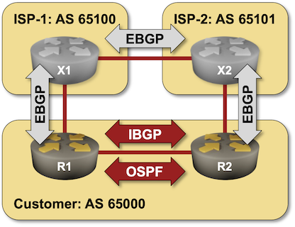
Most organizations want to optimize the utilization of their (still relatively expensive) WAN links. To do so, you’ll have to ensure that all your routers reach the destinations in ISP-1 via the R1-X1 uplink (and similarly for ISP-2).
Existing Lab Configuration
When starting the lab with netlab, you’ll get a preconfigured lab with EBGP sessions between the three autonomous systems and OSPF running between R1 and R2.
BGP Configuration
The routers in your lab use the following BGP AS numbers. Each upstream router advertises an IPv4 prefix; your routers advertise the IPv4 prefix of the LAN subnet connecting them.
| Node/ASN | Router ID | Advertised prefixes |
|---|---|---|
| AS65000 | ||
| r1 | 10.0.0.1 | 10.0.100.0/24 |
| r2 | 10.0.0.2 | 10.0.100.0/24 |
| AS65100 | ||
| x1 | 192.168.100.1 | 192.168.100.0/24 |
| AS65101 | ||
| x2 | 172.16.101.1 | 172.16.101.0/24 |
netlab configures these EBGP sessions when starting the lab; if you’re using some other lab infrastructure, you’ll have to configure EBGP neighbors and advertised prefixes manually.
| Node | Neighbor | Neighbor AS | Neighbor IPv4 |
|---|---|---|---|
| r1 | x1 | 65100 | 10.1.0.2 |
| r2 | x2 | 65101 | 10.1.0.10 |
| x1 | r1 | 65000 | 10.1.0.1 |
| x2 | 65101 | 10.1.0.6 | |
| x2 | x1 | 65100 | 10.1.0.5 |
| r2 | 65000 | 10.1.0.9 |
OSPF Configuration
OSPF running in the backbone area is configured on the following routers:
| Router | Interface | IPv4 Address | Neighbor(s) |
|---|---|---|---|
| r1 | Loopback | 10.0.0.1/32 | |
| Ethernet3 | 10.0.100.1/24 | r2 | |
| r2 | Loopback | 10.0.0.2/32 | |
| Ethernet3 | 10.0.100.2/24 | r1 |
Device Requirements
- Customer routers: use any device supported by the netlab BGP and OSPF configuration modules.
- Provider routers: use any device supported by the netlab BGP configuration module.
- You can do automated lab validation with Arista EOS or FRRouting running on R1 and R2.
Start the Lab
You can start the lab on your own lab infrastructure or in GitHub Codespaces (more details):
- Change directory to
ibgp/1-edge - Execute netlab up
- Log into your devices (R1, R2) with netlab connect and verify that netlab correctly configured their IP addresses, OSPF routing, and EBGP sessions.
Warning
If you’re not using netlab, you must configure R1 and R2 yourself.
Why Do We Need IBGP?
Inspect the BGP tables on R1 and R2. They contain the routes received from upstream ISPs but not those received by the other WAN router – R1 cannot use the R2-X2 uplink to reach ISP-2 (and vice versa for R2). The following printouts contain BGP tables on R1 and R2 (Arista vEOS generated all printouts in this lab exercise):
BGP table on R1
r1>show ip bgp | begin Network
          Network                Next Hop              Metric  AIGP       LocPref Weight  Path
 * >      10.0.100.0/24          -                     -       -          -       0       i
 * >      172.16.101.0/24        10.1.0.2              0       -          100     0       65100 65101 i
 * >      192.168.100.0/24       10.1.0.2              0       -          100     0       65100 i
BGP table on R2
r2>show ip bgp | begin Network
          Network                Next Hop              Metric  AIGP       LocPref Weight  Path
 * >      10.0.100.0/24          -                     -       -          -       0       i
 * >      172.16.101.0/24        10.1.0.10             0       -          100     0       65101 i
 * >      192.168.100.0/24       10.1.0.10             0       -          100     0       65101 65100 i
The content of the BGP tables on R1 and R2 shouldn’t surprise you; R1 and R2 are exchanging internal routes (using OSPF) but not external routes. We could “solve” the challenge by redistributing external routes into OSPF (hint: don’t do that), but then we’d lose the BGP information like the AS path the routers need to compare the routes.
The only sensible way forward is establishing a BGP session between R1 and R2. Because that session is set up between two routers in the same autonomous system, we call it an internal BGP (IBGP) session.
Establish IBGP Session
Configuration tasks:
- Configure an IBGP session between the loopback interfaces of R1 and R2 (10.0.0.1 and 10.0.0.2) using a BGP configuration command similar to neighbor address remote-as 65000.
Tip
You’ll find more details in the Configure a Single EBGP Session lab exercise.
- On some devices, you’ll have to activate the IBGP session within the IPv4 address family
Verification:
Check the status of the IBGP session with a command similar to show ip bgp summary or show ip bgp neighbors
The following printout contains the BGP summary information on R1 after configuring the IBGP session. As you can see, the router tries to establish the IBGP session but fails.
EBGP and IBGP neighbors on R1 (IBGP is not working)
r1#show ip bgp summary
BGP summary information for VRF default
Router identifier 10.0.0.1, local AS number 65000
Neighbor Status Codes: m - Under maintenance
  Description              Neighbor V AS           MsgRcvd   MsgSent  InQ OutQ  Up/Down State   PfxRcd PfxAcc
  r2                       10.0.0.2 4 65000              0         0    0    0 00:06:03 Active
  x1                       10.1.0.2 4 65100           2616      3068    0    0 02:10:34 Estab   2      2
Fix the Source IP Address of the IBGP Session
BGP uses TCP as the transport protocol, and without further configuration, the TCP session’s source IP address becomes the outgoing interface’s IP address. Attempts to establish an IBGP session using the source IP address of the LAN interface are rejected by the IBGP neighbor as the source IP address in the TCP SYN packet does not match the neighbor IP address configured on the remote router.
Configuration task:
- Configure the source address of the IBGP TCP session with a BGP configuration command similar to neighbor update-source.
Note
You could also configure the IBGP session between LAN IP addresses to make the lab work but never do that in a real-life network. You want the IBGP sessions to be stable, and the best way to achieve that goal is to use loopbacks as the endpoints of the TCP sessions (and rely on IGP to figure out how to reach remote loopbacks).
Verification:
After configuring the source IP address of the IBGP session on R1 and R2, the routers should be able to establish the IBGP session, as illustrated by the following printout:
EBGP and IBGP neighbors on R1 (after fixing the BGP source interface)
r1#show ip bgp summary
BGP summary information for VRF default
Router identifier 10.0.0.1, local AS number 65000
Neighbor Status Codes: m - Under maintenance
  Description              Neighbor V AS           MsgRcvd   MsgSent  InQ OutQ  Up/Down State   PfxRcd PfxAcc
  r2                       10.0.0.2 4 65000              8         8    0    0 00:00:07 Estab   2      2
  x1                       10.1.0.2 4 65100           2795      3276    0    0 02:19:28 Estab   2      2
After the IBGP session has been established, R1 and R2 exchange BGP prefixes received from X1 and X2, but the prefixes advertised by R2 are not selected as the best routes by R1 (and vice versa):
BGP table on R1 with a working IBGP session
r1#show ip bgp | begin Network
          Network                Next Hop              Metric  AIGP       LocPref Weight  Path
 * >      10.0.100.0/24          -                     -       -          -       0       i
 *        10.0.100.0/24          10.0.0.2              0       -          100     0       i
 * >      172.16.101.0/24        10.1.0.2              0       -          100     0       65100 65101 i
          172.16.101.0/24        10.1.0.10             0       -          100     0       65101 i
 * >      192.168.100.0/24       10.1.0.2              0       -          100     0       65100 i
          192.168.100.0/24       10.1.0.10             0       -          100     0       65101 65100 i
Further investigation shows that the IBGP prefixes are not used because they are considered invalid.
A BGP prefix advertised by EBGP and IBGP neighbors
r1#show ip bgp 172.16.101.0
BGP routing table information for VRF default
Router identifier 10.0.0.1, local AS number 65000
BGP routing table entry for 172.16.101.0/24
 Paths: 2 available
  65100 65101
    10.1.0.2 from 10.1.0.2 (192.168.100.1)
      Origin IGP, metric 0, localpref 100, IGP metric 0, weight 0, tag 0
      Received 00:07:37 ago, valid, external, best
      Rx SAFI: Unicast
  65101
    10.1.0.10 from 10.0.0.2 (10.0.0.2)
      Origin IGP, metric 0, localpref 100, IGP metric -, weight 0, tag 0
      Received 00:05:29 ago, invalid, internal
      Rx SAFI: Unicast
Arista EOS is not helpful in this scenario; you have to guess that the underlying root cause is that the BGP next hop is unreachable 1.
Fix the BGP Next Hop of IBGP Prefixes
BGP routers do not change the BGP next hop of EBGP routes when advertising them over IBGP – the BGP next hop of routes in AS 65101 as advertised by R2 to R1 is thus the IP address of X2 on the R2-X1 link (more details). R1 does not have a route to that IP subnet in its IP routing table, so it considers the IBGP prefix using that BGP next hop invalid.
There are two approaches to make the BGP next hop of IBGP prefixes valid:
- You can include the external subnets in the IGP process (for example, making them part of the OSPF area).
Warning
When using this approach, you must make the external subnets passive – you don’t want to run IGP routing with another autonomous system.
- You can change the BGP next hop of the prefixes advertised over IBGP to the IP address of the advertising router. We’ll use this approach.
Configuration task:
- Change the BGP next hop of prefixes advertised over IBGP sessions with a BGP configuration command similar to neighbor next-hop-self.
Verification:
Inspect the BGP tables and IP routing tables on R1 and R2 and verify that:
- R1 and R2 use BGP prefixes with the shortest AS path as the best BGP routes
- BGP-derived IP prefixes in the IP routing tables point to the WAN uplinks or the LAN link between R1 and R2.
You should get printouts similar to the ones generated by Arista EOS on R1:
BGP table on R1 with fixed BGP next hops
r1#show ip bgp | begin Network
          Network                Next Hop              Metric  AIGP       LocPref Weight  Path
 * >      10.0.100.0/24          -                     -       -          -       0       i
 *        10.0.100.0/24          10.0.0.2              0       -          100     0       i
 * >      172.16.101.0/24        10.0.0.2              0       -          100     0       65101 i
 *        172.16.101.0/24        10.1.0.2              0       -          100     0       65100 65101 i
 * >      192.168.100.0/24       10.1.0.2              0       -          100     0       65100 i
A BGP prefix advertised over IBGP has the correct BGP next hop
r1#show ip bgp 172.16.101.0
BGP routing table information for VRF default
Router identifier 10.0.0.1, local AS number 65000
BGP routing table entry for 172.16.101.0/24
 Paths: 2 available
  65101
    10.0.0.2 from 10.0.0.2 (10.0.0.2)
      Origin IGP, metric 0, localpref 100, IGP metric 20, weight 0, tag 0
      Received 00:00:29 ago, valid, internal, best
      Rx SAFI: Unicast
  65100 65101
    10.1.0.2 from 10.1.0.2 (192.168.100.1)
      Origin IGP, metric 0, localpref 100, IGP metric 0, weight 0, tag 0
      Received 00:51:03 ago, valid, external
      Rx SAFI: Unicast
The final IP routing table on R1
r1#show ip route | begin Gateway
Gateway of last resort is not set

 C        10.0.0.1/32 is directly connected, Loopback0
 O        10.0.0.2/32 [110/20] via 10.0.100.2, Ethernet3
 C        10.0.100.0/24 is directly connected, Ethernet3
 C        10.1.0.0/30 is directly connected, Ethernet1
 B I      172.16.101.0/24 [200/0] via 10.0.100.2, Ethernet3
 B E      192.168.100.0/24 [200/0] via 10.1.0.2, Ethernet1
Next:
Automated Verification
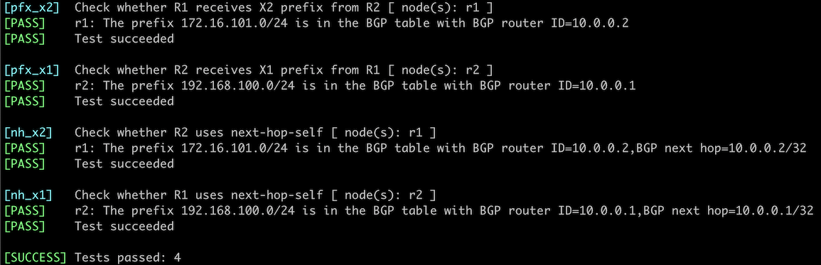
You can use the netlab validate command if you use FRRouting or Arista EOS on R1 and R2. The validation tests check whether R1 and R2 propagate the X1/X2 prefixes over the IBGP session and whether they change the BGP next hop to their loopback IPv4 addresses.
This is the printout you should get after completing the lab exercise:
Reference Information
This lab uses the 4-router lab topology. The following information might help you if you plan to build custom lab infrastructure:
Lab Wiring
| Link Name | Origin Device | Origin Port | Destination Device | Destination Port |
|---|---|---|---|---|
| WAN uplink R1-to-X1 | r1 | Ethernet1 | x1 | eth1 |
| WAN uplink R2-to-X2 | r2 | Ethernet2 | x2 | eth3 |
| Inter-ISP link X1-to-X2 | x1 | eth2 | x2 | eth2 |
| Intra-site LAN C1-C2 | r1 | Ethernet3 | r2 | Ethernet3 |
Note: Some interfaces are not used to conform with the predefined 4-router lab topology.
Lab Addressing
| Node/Interface | IPv4 Address | IPv6 Address | Description |
|---|---|---|---|
| r1 | 10.0.0.1/32 | Loopback | |
| Ethernet1 | 10.1.0.1/30 | WAN uplink R1-to-X1 | |
| Ethernet2 | |||
| Ethernet3 | 10.0.100.1/24 | Intra-site LAN C1-C2 | |
| r2 | 10.0.0.2/32 | Loopback | |
| Ethernet1 | |||
| Ethernet2 | 10.1.0.9/30 | WAN uplink R2-to-X2 | |
| Ethernet3 | 10.0.100.2/24 | Intra-site LAN C1-C2 | |
| x1 | 192.168.100.1/24 | Loopback | |
| eth1 | 10.1.0.2/30 | WAN uplink R1-to-X1 | |
| eth2 | 10.1.0.5/30 | Inter-ISP link X1-to-X2 | |
| eth3 | |||
| x2 | 172.16.101.1/24 | Loopback | |
| eth1 | |||
| eth2 | 10.1.0.6/30 | Inter-ISP link X1-to-X2 | |
| eth3 | 10.1.0.10/30 | WAN uplink R2-to-X2 |
Note: Some interfaces are not configured with IP addresses to conform with the predefined 4-router lab topology.
-
Some network devices consider any BGP next hop reachable if they have a default route. That can happen in a virtual lab if the lab device does not use a management VRF – most lab environments use DHCP to add the default route pointing to the management interface. When that default route appears in the global IP routing table, the IBGP prefix could be considered valid, but the resulting route would point to the management interface. ↩