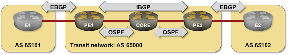
BGP-Free Core in a Transit Network
In the Build a Transit Network with IBGP lab exercise, you discovered why you must run BGP on every router in the forwarding path between two external autonomous systems. Some Internet Service Providers don’t want to have full Internet routing tables on their core routers and use a different approach: hide the transit traffic from the core routers by encapsulating it into a GRE/VXLAN tunnel or by sending it across the network in an MPLS virtual circuit (Label Switched Path – LSP). That’s what you’ll practice in this lab exercise.
Expert
This is an expert-level challenge lab – you are on your own. Good luck and Godspeed!
Device Requirements
- Use any device supported by the netlab BGP configuration module for the external routers.
- Use any router/switch supported by the netlab BGP and OSPF configuration modules for your devices. Check that the device you plan to use supports MPLS.
Warning
- Use cEOS release 4.31.2F or later to use MPLS with Arista EOS containers.
- SR Linux needs a license file to run MPLS.
- You cannot use MPLS with FRRouting or VyOS containers within GitHub Codespaces.
- Enabling MPLS data plane on FRRouting interfaces is not exactly trivial1.
Existing Routing Protocol Configuration
The routers in your lab use the following BGP AS numbers. All routers advertise their loopbacks2.
| Node/ASN | Router ID | Advertised prefixes |
|---|---|---|
| AS65000 | ||
| pe1 | 10.0.0.1 | |
| pe2 | 10.0.0.2 | |
| AS65101 | ||
| e1 | 192.168.101.1 | 192.168.101.0/24 |
| AS65102 | ||
| e2 | 192.168.102.1 | 192.168.102.0/24 |
Your devices have these BGP neighbors:
| Node | Router ID / Neighbor |
Router AS/ Neighbor AS |
Neighbor IPv4 |
|---|---|---|---|
| pe1 | 10.0.0.1 | 65000 | |
| pe2 | 65000 | 10.0.0.2 | |
| e1 | 65101 | 10.1.0.1 | |
| pe2 | 10.0.0.2 | 65000 | |
| pe1 | 65000 | 10.0.0.1 | |
| e2 | 65102 | 10.1.0.13 |
Your devices are running OSPF on intra-AS links. OSPF uses area 0 (the backbone area).
| Router | Interface | IPv4 Address | Neighbor(s) |
|---|---|---|---|
| pe1 | Loopback | 10.0.0.1/32 | |
| Ethernet2 | 10.1.0.6/30 | core | |
| pe2 | Loopback | 10.0.0.2/32 | |
| Ethernet1 | 10.1.0.10/30 | core | |
| core | Loopback | 10.0.0.3/32 | |
| Ethernet1 | 10.1.0.5/30 | pe1 | |
| Ethernet2 | 10.1.0.9/30 | pe2 |
netlab automatically configures IP addresses, OSPF, and BGP on your devices; if you’re using other lab infrastructure, you’ll have to configure them manually.
Start the Lab
You can start the lab on your own lab infrastructure or in GitHub Codespaces (more details):
- Change directory to
challenge/40-mpls-core - Execute netlab up
- Log into your devices with netlab connect and verify that the IP addresses, OSPF routing, and the BGP sessions are properly configured.
Warning
LDP daemon (ldpd) must be running on FRRouting MPLS core routers (PE1, PE2, and CORE in AS65000). netlab starts it for you, but you should still check whether it’s enabled using this procedure (looking for ldpd).
The Problem
After the OSPF adjacencies in the transit autonomous system are established, E1 receives the BGP prefix advertised by E2 (and vice versa):
e1# show ip bgp
BGP table version is 4, local router ID is 192.168.101.1, vrf id 0
Default local pref 100, local AS 65101
Status codes:  s suppressed, d damped, h history, * valid, > best, = multipath,
               i internal, r RIB-failure, S Stale, R Removed
Nexthop codes: @NNN nexthop's vrf id, < announce-nh-self
Origin codes:  i - IGP, e - EGP, ? - incomplete

   Network          Next Hop            Metric LocPrf Weight Path
*> 192.168.101.0/24 0.0.0.0(e1)              0         32768 i
*> 192.168.102.0/24 10.1.0.2                               0 65000 65102 i

Displayed  4 routes and 4 total paths
However, you can’t ping E2 from the loopback address of E1:
e1(bash)#ping -I 192.168.101.1 192.168.102.1
PING 192.168.102.1 (192.168.102.1) from 192.168.101.1: 56 data bytes
^C
--- 192.168.102.1 ping statistics ---
8 packets transmitted, 0 packets received, 100% packet loss
A traceroute executed on E1 indicates that the probe packets arrive at PE1 and then get dropped by the CORE router. You shouldn’t be surprised by that behavior; the CORE router is not running BGP and has no route to E1 or E2.
e1(bash)#traceroute -s 192.168.101.1 192.168.102.1
traceroute to 192.168.102.1 (192.168.102.1) from 192.168.101.1, 30 hops max, 46 byte packets
 1  10.1.0.2 (10.1.0.2)  0.002 ms  0.002 ms  0.001 ms
 2  *  *  *
Tip
You must execute ping and traceroute between loopback IP addresses of E1 and E2. The syntax of extended ping and traceroute commands differs across network devices; on Linux, use ping -I $locip $remoteip and traceroute -s $locip $remoteip.
Configuration Hint
You must configure MPLS transport across AS 65000 to hide transit traffic into an MPLS LSP. To do this, you can use the Label Distribution Protocol or MPLS-based Segment Routing (SR/MPLS) using OSPF.
Warning
- If you’re using FRRouting containers, execute
sudo modprobe mpls-router mpls-iptunnelbefore starting the lab. - You must use
sysctlcommands to enable MPLS on FRRouting interfaces (see FRRouting OSPF Segment Routing documentation for more details).
Verification
After setting up MPLS transport across AS 65000, you should see MPLS labels attached to BGP routes on PE1 and PE2 (printout from Arista vEOS):
pe1#show ip route bgp
...

 B E      192.168.101.0/24 [200/0] via 10.1.0.1, Ethernet1
 B I      192.168.102.0/24 [200/0] via 10.0.0.2/32, LDP tunnel index 2
                                      via 10.1.0.5, Ethernet2, label 100001
ping and traceroute between E1 and E2 should work. Depending on how you configured the CORE device, you might not see it in the traceroute printout:
vagrant@e1:mgmt:~$ ping 192.168.102.1 -I 192.168.101.1
vrf-wrapper.sh: switching to vrf "default"; use '--no-vrf-switch' to disable
PING 192.168.102.1 (192.168.102.1) from 192.168.101.1 : 56(84) bytes of data.
64 bytes from 192.168.102.1: icmp_seq=1 ttl=61 time=11.9 ms
64 bytes from 192.168.102.1: icmp_seq=2 ttl=61 time=9.78 ms
64 bytes from 192.168.102.1: icmp_seq=3 ttl=61 time=9.47 ms
64 bytes from 192.168.102.1: icmp_seq=4 ttl=61 time=11.2 ms
64 bytes from 192.168.102.1: icmp_seq=5 ttl=61 time=10.3 ms
^C
--- 192.168.102.1 ping statistics ---
5 packets transmitted, 5 received, 0% packet loss, time 11ms
rtt min/avg/max/mdev = 9.470/10.557/11.949/0.930 ms

vagrant@e1:mgmt:~$ traceroute 192.168.102.1 -s 192.168.101.1
vrf-wrapper.sh: switching to vrf "default"; use '--no-vrf-switch' to disable
traceroute to 192.168.102.1 (192.168.102.1), 30 hops max, 60 byte packets
 1  10.1.0.2 (10.1.0.2)  2.066 ms  2.227 ms  2.810 ms
 2  * * *
 3  10.1.0.10 (10.1.0.10)  13.077 ms  14.636 ms  16.515 ms
 4  10.1.0.13 (192.168.102.1)  18.186 ms  20.036 ms  22.695 ms
Reference Information
Lab Wiring
| Origin Device | Origin Port | Destination Device | Destination Port |
|---|---|---|---|
| e1 | eth1 | pe1 | Ethernet1 |
| pe1 | Ethernet2 | core | Ethernet1 |
| core | Ethernet2 | pe2 | Ethernet1 |
| pe2 | Ethernet2 | e2 | eth1 |
Lab Addressing
| Node/Interface | IPv4 Address | IPv6 Address | Description |
|---|---|---|---|
| core | 10.0.0.3/32 | Loopback | |
| Ethernet1 | 10.1.0.5/30 | core -> pe1 | |
| Ethernet2 | 10.1.0.9/30 | core -> pe2 | |
| e1 | 192.168.101.1/24 | Loopback | |
| eth1 | 10.1.0.1/30 | e1 -> pe1 | |
| e2 | 192.168.102.1/24 | Loopback | |
| eth1 | 10.1.0.13/30 | e2 -> pe2 | |
| pe1 | 10.0.0.1/32 | Loopback | |
| Ethernet1 | 10.1.0.2/30 | pe1 -> e1 | |
| Ethernet2 | 10.1.0.6/30 | pe1 -> core | |
| pe2 | 10.0.0.2/32 | Loopback | |
| Ethernet1 | 10.1.0.10/30 | pe2 -> core | |
| Ethernet2 | 10.1.0.14/30 | pe2 -> e2 |
-
If you use FRRouting containers, you have to load the MPLS-related kernel modules on the Linux host before starting the lab. netlab does that when you use the mpls module, but doing that would defeat the purpose of this lab exercise. ↩
-
Loopbacks of PE1 and PE2 won’t be advertised to adjacent autonomous systems if you’re running a recent version of FRRouting (more details). ↩